Textured Geomembrane
HDPE / LLDPE Lining Membrane — Textured Surface
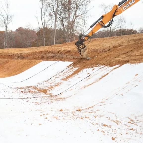
The low friction coefficient of a smooth geomembrane turns into a disadvantage on steep slopes: the geotextile, drainage layer or waste mass placed on top of it tends to slide. A textured geomembrane raises the interface friction angle through the asperities given to its surface, and prevents that sliding.
- Category
- Lining & Sealing
- Product Group
- HDPE / LLDPE Lining Membrane — Textured Surface
- Product Code
- TX-HDPE / TX-LLDPE
A slope stays stable only if every layer on it grips the one beneath sufficiently. A smooth-surfaced membrane cannot provide that grip on steep gradients; the result is interface slippage, a problem frequently seen in geotechnical projects. Textured geomembrane rests on the same GRI-GM13 (HDPE) and GRI-GM17 (LLDPE) base specifications, but the asperities added to its surface are produced so as to deliver safe interface friction in slope, berm and steep-fill applications.
What is a Textured Geomembrane?
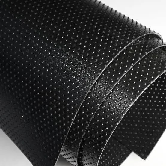
A textured geomembrane is produced from the same base raw material as a smooth one (HDPE or LLDPE); the difference lies in the texturing process applied to the surface during extrusion. Two methods are used in production:
**Co-extrusion (nitrogen-injected) texturing:** Nitrogen gas is injected into the molten polymer in the extruder and the mixture is homogenised along the screw; as the melt leaves the die, the nitrogen expands and creates an irregular asperity pattern on the surface. This method can be applied to one or both faces.
**Impingement (spray) texturing:** Asperities are formed by spraying droplets of molten polymer onto the surface of the cooling base sheet; this method gives a more controlled asperity distribution.
In both methods the roll edges are left relatively smooth in order to make field welding easier. Asperity height is verified by the ASTM D7466 test method (measured at 10 randomly selected points across the roll width); this method has replaced the older GRI-GM12 test procedure. The textured line is produced in both HDPE and LLDPE formulations, with single-sided or double-sided texturing: single-sided is used where only the upper layer (geotextile, drainage layer) is in contact; double-sided is preferred in applications requiring interface friction with both the subgrade and the layer above.
Why this material?
It raises the slope angle and shrinks the site footprint
Where the interface friction angle on a smooth geomembrane is typically 10°–20°, on a textured surface it rises to 25°–40° (measured by the ASTM D5321 direct shear test). A steeper slope design makes it possible to store the same volume on a smaller area — which directly lowers excavation and land costs.
It reduces anchoring and excavation costs
When slope stability is delivered by interface friction, the need for additional stabilisation measures (wider berms, extra anchor trenches) falls away.
It provides a safety margin on waste and mine sites
Interface friction carries the sliding risk that grows as fill height increases; this is a critical design parameter at sanitary landfills and on heap leach pads.
It preserves the same chemical and UV performance
Texturing changes only the surface geometry; the carbon black content, OIT and chemical resistance requirements under GRI-GM13/GM17 are identical to those of the smooth type.
Where does it work on site?
Solid, Medical and Hazardous Waste Sites
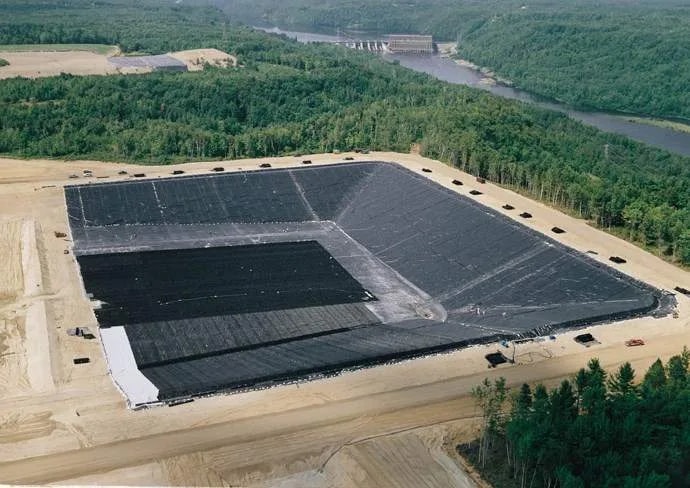
On the side slopes of sanitary landfills (generally graded between 1/3 and 1/2), a textured geomembrane becomes mandatory in order to prevent the waste mass and the drainage/protection layers above it from sliding. In Turkey the Regulation on the Landfilling of Waste requires cell slope gradients to be no steeper than 1/3; at that gradient the sliding risk of the drainage layer — which must remain stationary on a smooth-surfaced membrane — is substantially reduced by a textured surface.
Ponds and Pools
In sloped ponds, particularly on projects where the water level fluctuates, the textured type is preferred on the slope sections so that the protection layer or concrete paving placed over the geomembrane does not slide. The base section can remain smooth.
Mine Sites
On heap leach pads and tailings dams, slope angles generally vary between 1/2 and 1/1.5; at these steep gradients, interface friction is a critical design parameter at both the geomembrane–geotextile and the geomembrane–drainage gravel interfaces. In mining engineering projects the interface friction angle is generally the governing input to slope stability calculation.
Oil Fields and Tank Farms
A textured surface is used on the secondary containment berms around tanks and on the sloped sections of containment areas, so that the fill or protection material laid over it stays in place.
Irrigation and Water Conveyance Canals
In deep-section canals, the steeper the slope angle the greater the risk that the stone or concrete lining placed over the geomembrane will slide. In these sections the textured type reduces the need for additional anchoring and allows the canal section to be designed more economically.
Measured values.
The values below are typical/minimum limits. A lot-specific certified test report should be requested before ordering.
| Property | Test Standard | HDPE Type | LLDPE Type |
|---|---|---|---|
| Formulated density | ASTM D792 | ≥ 0,940 g/ml | ≤ 0,939 g/ml |
| Thickness range | ASTM D5199 | 0,75 – 3,00 mm | 0,50 – 3,00 mm |
| Surface type | — | Single/double-sided textured | Single/double-sided textured |
| Asperity height | ASTM D7466 | ≥ 0.25 mm (typ. 0.3–0.8 mm) | ≥ 0.25 mm (typ. 0.3–0.8 mm) |
| Interface friction angle | ASTM D5321 | ~25° – 40° | ~25° – 40° |
| Carbon black content | ASTM D1603 / D4218 | %2,0 – 3,0 | %2,0 – 3,0 |
| Elongation at break | ASTM D6693 | ≥ %100 (tipik %200 – 400) | ≥ %250 (tipik %250 – 450) |
| Standard OIT | ASTM D3895 | ≥ 100 dk | ≥ 100 dk |
| High-Pressure OIT | ASTM D5885 | ≥ 400 dk | ≥ 400 dk |
| Permeability | ASTM D5084 | ≤ 1×10⁻¹¹ cm/sn | ≤ 1×10⁻¹¹ cm/sn |
Thickness-dependent mechanical values (tensile, tear and puncture strength) are defined in the GRI-GM13/GM17 textured-product tables as separate minimum average roll values (MARV) for each thickness. Prior to ordering, the current Manufacturing Quality Control (MQC) report and the interface friction test result (ASTM D5321) for the relevant thickness and texturing type should be requested.
| Parameter | HDPE Type | LLDPE Type |
|---|---|---|
| Roll width | 2 – 7 m | 2 – 7 m |
| Roll length | 50 – 100 m | 50 – 150 m |
| Edge treatment | Smooth edge for welding | Smooth edge for welding |
| Colour | Black (standard) | Black (standard) |
In brief
- Asperity height produced by co-extrusion or impingement, verified by ASTM D7466
- Single-sided or double-sided texturing options
- An interface friction angle measured by the ASTM D5321 direct shear test, reaching 2–2.5 times that of the smooth type
- A resin structure meeting the same GRI-GM13/GM17 chemical and UV resistance requirements
- Smoothed roll edges that make field welding easier
- Two material lines, HDPE and LLDPE, selectable according to project gradient
Test standards
- GRI-GM13
- Specification for HDPE Smooth and Textured Geomembranes
- GRI-GM17
- Specification for LLDPE Smooth and Textured Geomembranes
- ASTM D7466
- Test Method for Asperity Height of Textured Geomembranes
- ASTM D5321
- Test Method for Geosynthetic Interface Direct Shear
- EN 13361
- Geosynthetic Barriers for Use in the Construction of Dams and Reservoirs
- TR Yönetmelik
- Turkish Regulation on Sanitary Landfilling of Waste — impermeable layer and slope gradient requirements
- ASTM
- D792, D5199, D6693, D1004, D4833, D1603/D4218, D3895, D5885, D5084
Rolls are dispatched on wooden cores, wrapped in stretch film to protect the textured surface against dust or dirt accumulation. They should be stored indoors, away from direct sunlight.
- The values above are minimum limit values from the GRI-GM13/GM17 textured-product tables; certified test results specific to thickness and texturing type (particularly the ASTM D5321 interface friction angle) are available on request for our product family.
- Slope stability calculations must be based on actual interface friction tests performed with the project-specific interface material (geotextile, GCL, drainage composite, etc.); the angle range in this catalogue is a general reference.
- The choice between single-sided and double-sided texturing is determined by the project installation detail.
“Slope safety is verified by project-specific interface friction testing, not by assumption — our test results are shared on request.”
A choice grounded in data.
Geoals textured geomembrane is bound to a production discipline in which asperity height is verified to ASTM D7466 at 10 random points across the roll — this keeps texturing quality consistent along the roll and from roll to roll. For the geotechnical engineer performing a slope stability calculation, what matters is not the asperity height of a single sample but the reliable repeatability of that value across the entire delivery.
Frequently asked
What is the fundamental difference between a textured and a smooth geomembrane?
The difference is in surface geometry. The asperities added to the surface of the textured type raise the interface friction angle from 10°–20° to 25°–40°, which prevents the layers above it from sliding on steep slopes. The chemical and UV resistance requirements are identical for both types.
At what slope gradient is a textured geomembrane required?
The exact threshold depends on the slope stability calculation; in practice, however, the textured type becomes standard on gradients steeper than 1/3. In Turkey, cell slope gradients at sanitary landfills are limited by regulation to a maximum of 1/3, and at that gradient a textured surface is preferred in practice.
Should I choose single-sided or double-sided texturing?
If interface friction is required only with the layer above the geomembrane (a geotextile, for instance), single-sided is sufficient. Double-sided is preferred in steep-slope applications requiring friction with both the subgrade and the layer above.
How is asperity height measured, and what value is sufficient?
Asperity height is measured by the ASTM D7466 test method at 10 randomly selected points across the roll width. The minimum value widely accepted in the industry is 0.25 mm; the typical production range is 0.3–0.8 mm. The required value is determined by the project engineer according to the interface friction angle calculation.
Why is a textured geomembrane more expensive than the smooth type?
Texturing adds a further processing step (nitrogen injection or impingement) to the extrusion line and lowers production speed; for this reason the textured type typically costs 10–20% more than the smooth type.
Why is the break elongation of a textured geomembrane lower than that of the smooth type?
The polymer structure at the surface is altered during texturing; this reduces break elongation from 700% and above in the smooth type to a typical range of 200–400% in the textured type (the specification minimum is 100%). This reduction is separately defined in the textured tables of GRI-GM13/GM17 and is designed to meet project requirements in terms of strength.
Your slope angle, fill height and interface material are specific to your project — and so are the right texturing method and asperity height. Request a technical quote suited to your slope stability data, together with an ASTM D5321 interface friction report, from the Geoals technical team.