Geocell
HDPE Cellular Confinement System
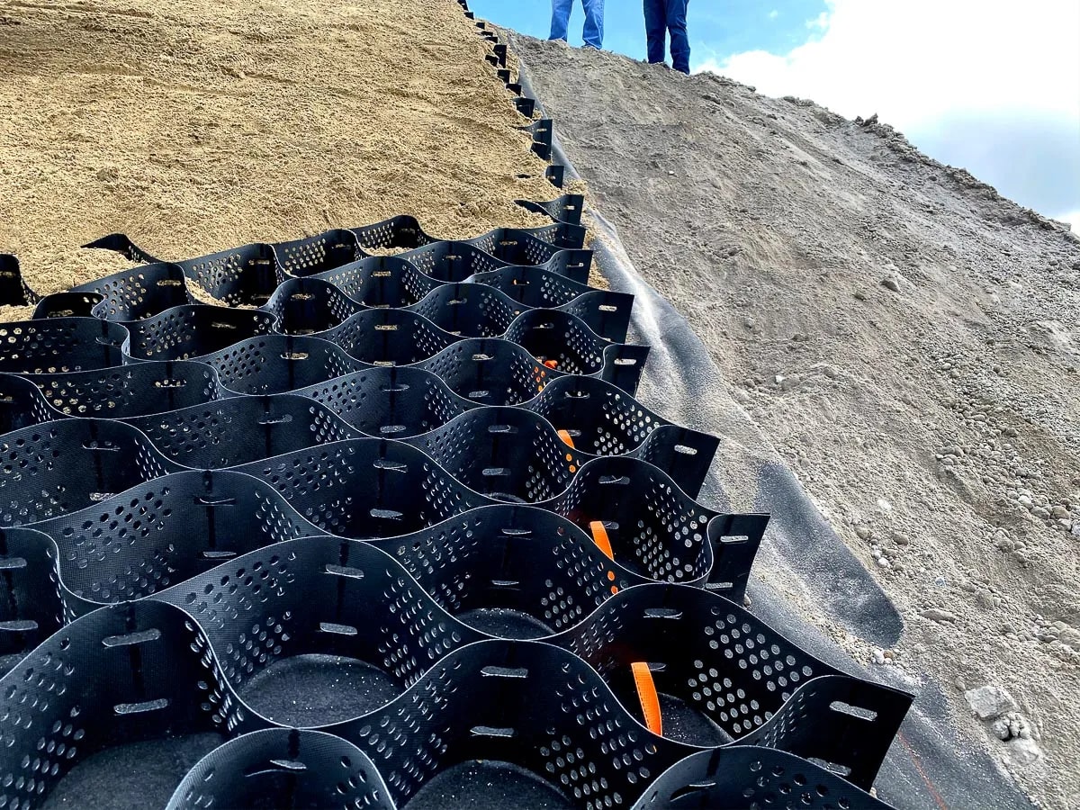
Soil on a slope moves over time under gravity and surface water — vegetation can only arrest that movement up to a certain gradient and flow velocity. A geocell is a three-dimensional cellular network formed by joining HDPE strips with ultrasonic welds and expanding them into a honeycomb; by holding the infill (soil, aggregate, concrete) in place, it creates a durable surface that can be vegetated, both on steep slopes and on channel faces.
- Category
- Stabilisation
- Product Group
- HDPE Cellular Confinement System
- Product Code
- GC-HDPE
The idea of a cellular confinement system is not new — it was developed by the US Army Corps of Engineers in the 1980s to allow heavy vehicles to move over sandy, loose ground. The geocell carries that same principle (raising the apparent strength of infill material through lateral confinement) into civil engineering: slope erosion control, channel linings, soil stabilisation, and permanent earth structures on steep slopes.
What is a Geocell?
A geocell is produced by joining strips of high-density polyethylene (HDPE) with ultrasonic welds at set intervals. The strips are shipped to site folded and packed; when opened on site they expand like an accordion to form a honeycomb-shaped three-dimensional cellular structure. The cell walls are produced both textured and perforated: the texture raises friction between the infill and the wall, allowing the material to interlock better within the cell; the perforations allow drainage and let plant roots spread into neighbouring cells.
The load-bearing capacity of the system comes not from the cell wall itself but from the strength of the weld (seam) points — because in slope and wall applications the load reaching the seams is higher than the load reaching the wall. Seam strength is therefore tested separately to ISO 13426-1 (Method C) and expressed in N/m. Cell depth typically varies between 50 and 300 mm (the most commonly used depths are 75, 100, 150 and 200 mm); wall thickness is selected between 1.0 and 2.0 mm according to the load level of the application.
Why this material?
Bearing capacity raised by lateral confinement
The cell walls prevent the infill inside them from moving laterally; this confinement effect raises the apparent friction angle of the fill and therefore its bearing capacity. Loads are spread across a wider area through the cellular network, rather than into a single contact point.
Natural drainage prevents hydrostatic build-up
The perforated structure of the cells prevents water from accumulating within the soil and creating hydrostatic pressure; this is an important factor in reducing the risk of sliding, particularly on slopes.
A surface that can be vegetated
Soil-filled cells allow plant roots to develop; this delivers both erosion control and the environmental and visual integration of the project.
Different performance levels from different infill
The same cellular system can be filled with stone, soil or concrete and adapted to different flow velocity and load conditions — offering a wide application range from a single product family.
Where does it work on site?
Creating Permanent Earth Structures
On steep slopes where cellular panels cannot be laid horizontally across the face, geocells are built as vertical walls to retain the soil. In this application the cells do not merely hold the soil — they continue to perform a drainage function for the life of the structure. This is an important difference from conventional retaining walls, because drainage problems are the root cause of most retaining structure failures.
Channel Lining Applications
In channels where flow velocity exceeds a certain threshold, bare soil or vegetation alone is insufficient — an earth channel not protected by vegetation generally begins to carry an erosion risk above roughly 0.6 m/s. In grass-lined channels with geocell, the system keeps the soil infill in place and allows the vegetation to withstand far higher flow velocities; depending on the infill and the choice of a supporting erosion mat, this figure can rise several-fold. On steep channel slopes, the flexibility of the geocell also makes it easier to hold concrete infill in place; in that case the channel can accommodate ground movement without the joint and crack risks of a cast concrete structure.
Soil Stabilisation
The cell walls hold the aggregate together by preventing its lateral movement under applied loads. The load is distributed across a wider area through the cellular network rather than into a single contact point. The cellular geometry also provides a natural drainage structure, preventing the infill from being damaged by hydraulic flows and stopping forces from working into the soil and building hydrostatic pressure.
Slope Erosion Protection
Placed on steep slopes, a geocell retains the infill and limits its movement. This function removes the formation of rilling — a significant cause of erosion — because surface water spreads and flows between the fixed cell walls, and never gets the chance to accelerate along a single rill and cut into the soil.
Measured values.
The values below are typical/minimum limits. A lot-specific certified test report should be requested before ordering.
| Property | Test Standard | Typical Value |
|---|---|---|
| Raw material | — | HDPE |
| Wall thickness | — | 1,0 – 2,0 mm |
| Cell depth | — | 50 – 300 mm (common: 75/100/150/200 mm) |
| Cell size (before expansion) | — | ~220 – 500 mm |
| Surface | — | Textured + perforated |
| Seam (junction) strength | ISO 13426-1 (Yöntem C) | ≥ 14.2 N/mm of cell depth (≥ 1,420 N for a 100 mm cell) |
| Carbon black content | ASTM D1603 / D4218 | %1,5 – 2,0 |
| Environmental stress cracking (ESCR) | ASTM D1693 | ≥ 3,000 hours (typical specification value) |
| Density | ASTM D792 | ≥ 0,94 g/ml |
Seam strength is the critical parameter defining the system's true load limit; the weld junctions carry higher loads than the cell wall itself. Prior to ordering, the ISO 13426-1 test report for the relevant depth/thickness series should be requested.
| Infill Material | Flow Velocity Resistance |
|---|---|
| Bare soil (reference, without geocell) | Risk above ~0.6 m/s |
| Angular stone | Up to ~3 m/s |
| Vegetated soil | Up to ~6 m/s |
| Concrete infill | ~7 m/s and above |
| Parameter | Value |
|---|---|
| Shipping condition | Folded (unexpanded) panel |
| Panel expansion | Accordion type, expanded by hand on site |
| Weight | Light, can be carried manually |
| Accessories | Anchor stake/clip, panel connection element |
In brief
- HDPE strips joined by ultrasonic welding, transported folded and expanded on site
- Textured and perforated cell walls: infill interlock plus natural drainage
- Seam strength tested to ISO 13426-1 — the parameter that sets the system's real load limit
- Cell depths from 50 to 300 mm, selected by load and application type
- Multi-purpose use with stone, soil or concrete infill
- Erosion control and landscape integration together, thanks to a structure that can be vegetated
Test standards
- ISO 13426-1
- (Method C) Test Method for Geocell Junction Strength
- ASTM D792
- Density
- ASTM D1603 / D4218
- Carbon Black Content
- ASTM D1693
- Environmental Stress Crack Resistance (ESCR)
- ASTM D4355
- UV Resistance
- ASTM D638
- Tensile Properties of HDPE Sheet
As panels are shipped folded, they require little storage space. Installation needs no heavy machinery or concrete foundation; panels are fixed with anchor stakes and filled with the chosen infill material.
- Seam strength must be tested separately, independently of wall thickness; in slope and wall applications the load on the junctions exceeds the load on the wall.
- In channel applications, flow velocity reference values must be verified by project-specific hydraulic calculation according to flow duration and channel gradient.
- The perforated cell wall enables drainage and root development but slightly reduces strength compared with a solid wall; this effect must be considered in design for high-load applications.
- Certified test results specific to cell depth and wall thickness are available on request.
“In geocell systems the true limit is set by the weld junction — we provide an ISO 13426-1 test report for every series.”
A choice grounded in data.
The performance of a geocell rests on the strength of its seams, not its cell walls — a detail often overlooked, yet the real cause of field failures. Choosing a product whose seam strength is documented to ISO 13426-1 is the precondition of long-term performance in slope and wall applications.
Frequently asked
What is the difference between a geocell and a conventional retaining wall?
Conventional retaining walls are generally rigid structures, and drainage problems are the most frequent cause of their failure. The perforated cell structure of a geocell provides continuous drainage for the life of the structure; this prevents hydrostatic build-up and the structural damage that follows from it.
How is cell depth chosen?
Depth is determined by the load to be carried and the type of application. While 75–100 mm may be sufficient for erosion control and light soil stabilisation, depths of 150–200 mm and above are preferred for heavily loaded soil stabilisation or high retaining walls.
What should a geocell be filled with?
Soil infill is suitable for vegetation and erosion control. Angular stone infill is preferred in channels with moderate flow velocity. Concrete infill is used in channel and slope applications requiring high flow velocity or permanent hardness.
Up to what flow velocity is a geocell sufficient in a channel?
This depends on the infill: vegetated soil infill can be used up to several m/s, angular stone infill up to roughly 3 m/s, and concrete infill at flow velocities of 7 m/s and above. The exact design value must be determined by hydraulic calculation according to channel gradient and flow duration.
What actually determines a geocell's load-bearing capacity?
Not the wall itself, but the weld (seam) points where the strips join — because in slope and wall applications the load reaching the seam is higher than the load reaching the wall. When selecting a geocell, seam strength (ISO 13426-1) is therefore a more decisive criterion than wall thickness alone.
Is special equipment required to install a geocell?
No. Because the system is light it can be carried by hand and is easily installed on site by expanding it from its folded state; it requires no heavy plant or concrete foundation.
The right cell depth and infill for your slope, channel or soil stabilisation requirement follow from your load and flow conditions. Request a project-specific technical quote and a seam strength test report from the Geoals technical team.