Geonet & Drainage Geocomposite
HDPE Geonet / Geonet-Geotextile Composite Drainage Material
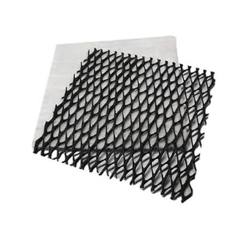
The traditional way to drain water from a site is a 50 cm layer of gravel — heavy, bulky and expensive to haul. A geonet delivers the same hydraulic conductivity in a section a few millimetres thick, through the three-dimensional net formed by intersecting HDPE ribs. The non-woven geotextile laminated to it prevents fine-grained material from clogging the net channels, and so preserves that flow capacity over time.
- Category
- Drainage
- Product Group
- HDPE Geonet / Geonet-Geotextile Composite Drainage Material
- Product Code
- GN-BI (Biplanar) / GN-TRI (Triplanar)
A drainage layer has one job: to carry water (or gas) away quickly, without clogging, for the design life of the system. A drainage geocomposite performs that job in a far thinner section than a conventional gravel/aggregate layer; even Turkey's Regulation on the Landfilling of Waste explicitly states that geosynthetic drainage material may be used, alongside natural material, for the capping (top cover) drainage layer. This is the technical basis of the geocomposite's “cost-effective” position: delivering equivalent drainage capacity with far less excavation and haulage volume.
What is a Geonet & Drainage Geocomposite?
A geonet is produced on an HDPE extrusion line by intersecting two or three sets of parallel ribs at defined angles. In the **biplanar** structure, two equal rib sets are laid at an angle to the machine direction (MD) and intersect to form diamond-patterned flow channels. In the **triplanar** structure, cross-laid support ribs are added above and below a set of straight ribs that channel the flow in the middle; this additional layer prevents the geotextile from intruding into the net channels under load, and so maintains stable hydraulic performance in the long term — which is why the triplanar type is preferred for leachate drainage under high pressure (beneath a mine heap or a deep waste fill, for example).
The hydraulic performance of a geonet is measured as in-plane flow capacity (transmissivity) and documented by ASTM D4716/D4716M (constant-head test method for in-plane flow rate and transmissivity), or by its European equivalent, ISO 12958. This value falls as the pressure applied to the material increases (as it does beneath a deep fill); for this reason a transmissivity value must always be stated together with the pressure and hydraulic gradient conditions at which it was measured.
**The geotextile lamination has two distinct functions.** The first is filtration: laminated to the face in contact with fine-grained fill or the upper surface of the waste, the geotextile prevents fine particles from migrating into the net channels and causing clogging. The second is a question of interface strength that is often overlooked: the friction angle of a geonet–geomembrane interface is markedly lower than that of a geotextile–textured geomembrane interface. The geotextile lamination therefore functions not only as filtration but as a safety element that raises interface sliding resistance in sloped applications.
Why this material?
It delivers the same capacity in far less volume
A geocomposite drainage layer can offer, in a section a few millimetres thick, transmissivity equal to or greater than that of a gravel layer metres deep; this directly reduces excavation depth and aggregate haulage cost.
An alternative recognised by regulation
Turkey's landfill regulation explicitly accepts geosynthetic material, alongside natural material, for the capping drainage layer; this shows that a geocomposite is a valid option in terms of regulatory compliance as well as engineering preference.
Stable performance under pressure (triplanar type)
The central channelling ribs and the supporting cross layers limit the intrusion of the geotextile into the net channels even under a high fill load, and so preserve transmissivity over time.
Filtration and interface strength in one
The laminated geotextile both prevents fine material from causing clogging and raises sliding resistance in sloped applications over a geomembrane — a single layer performing two distinct functions.
Where does it work on site?
Mine Sites
On heap leach pads, the weight of the ore heap applies a high and continuous pressure to the drainage layer. In this condition a triplanar geonet is preferred, because its central channelling structure preserves solution-collection capacity even under pressure. The geocomposite both accelerates the collection of valuable metal solution and limits the hydrostatic load on the geomembrane liner.
Solid, Hazardous and Municipal Waste Landfills
On these sites a drainage geocomposite can serve in three distinct positions: **(1)** as the primary leachate collection layer above the base liner — it can meet the regulatory requirement of a minimum 50 cm thickness and K≥1.0×10⁻⁴ m/s permeability with equivalent or superior performance in a far thinner section; **(2)** as a leak detection layer between two geomembranes in double-liner designs; **(3)** in the post-closure top cover, as the capping drainage layer that carries rainwater away from the upper geomembrane — this is precisely where the regulation explicitly permits geosynthetic material. At facilities where gas generation is expected, the same geocomposite structure can also be designed as a gas drainage/venting layer.
Dam Reservoirs and Embankments
Used within an embankment dam body for internal drainage (chimney drain, toe drain), it discharges seepage water that may accumulate inside the body in a controlled manner and prevents the build-up of hydrostatic pressure and the associated rise in pore water pressure — a critical function in controlling slope stability and the risk of internal erosion (piping) in fill dams. Used beneath a geomembrane on the reservoir base, it forms an additional safety layer for leak detection and discharge.
Measured values.
The values below are typical/minimum limits. A lot-specific certified test report should be requested before ordering.
| Property | Test Standard | Typical Value |
|---|---|---|
| Raw material | — | HDPE |
| Structure type | — | Biplanar / Triplanar |
| Thickness | ASTM D5199 | ~4 – 10 mm |
| Transmissivity | ASTM D4716/D4716M / ISO 12958 | Typically 1×10⁻⁴ – 2×10⁻³ m²/s (pressure- and gradient-dependent) |
| Compressive resistance (short-term) | ASTM D6364 | Series selected per project load; value stated in the MQC report |
| Carbon black content | ASTM D1603 / D4218 | ~%2,0 |
| Density | ASTM D792 | ≥ 0,94 g/ml |
| Geocomposite ply adhesion | ASTM D7005 | Between laminated geotextile and geonet |
Transmissivity is not meaningful independently of test pressure and hydraulic gradient. Prior to ordering, test data measured at the pressure level closest to the project's actual load condition should be requested.
| Parameter | Value |
|---|---|
| Roll width | ~2 – 6,7 m |
| Roll length | Varies with type and thickness |
| Geotextile overlap (composite type) | ~10 cm |
In brief
- Biplanar and triplanar structures, suited to different load and flow scenarios
- Transmissivity documented to ASTM D4716/D4716M, measured under pressure
- Non-woven geotextile lamination providing filtration and interface strength together
- A geosynthetic alternative to the gravel drainage layer, accepted by regulation
- HDPE raw material with UV stability provided by 2% carbon black
- Multi-purpose use on mine, landfill, dam and waste sites from the same base structure
Test standards
- ASTM D4716/D4716M
- In-Plane Flow Rate and Transmissivity (Constant Head Method)
- ISO 12958
- Transmissivity (EN/ISO Equivalent)
- ASTM D6364
- Short-Term Compressive Behaviour
- ASTM D1603 / D4218
- Carbon Black Content
- ASTM D5199
- Thickness
- ASTM D792
- Density
- ASTM D7005
- Geocomposite Ply Adhesion (Peel) Strength
- TR Yönetmelik
- Turkish Regulation on Sanitary Landfilling of Waste — drainage layer thickness/permeability requirement, geosynthetic alternative permission
Rolls should be wrapped in stretch film and stored in an enclosed, dry area. During installation, care must be taken to lay the material in the correct orientation, with the geotextile face in contact with the soil/aggregate.
- The triplanar type is recommended for applications under high, sustained pressure (mine heaps, deep waste fills) to preserve transmissivity in the long term.
- Geotextile lamination provides both filtration and interface shear strength; on slopes, note that the geonet–geomembrane interface exhibits lower friction than the geotextile–geomembrane interface.
- Before use in landfills, the function of the relevant layer (primary drainage / leak detection / closure drainage) should be clarified and the product type selected accordingly.
- Definitive transmissivity and ply-adhesion values are documented in the product-series-specific MQC report.
“We measure transmissivity at your project's actual load condition and document the result in a report.”
A choice grounded in data.
Selecting a drainage geocomposite correctly begins not with reading a single transmissivity number, but with understanding the pressure and gradient conditions at which that number was measured. The same product may perform excellently in a surface drainage application and fall far short of expectations beneath a deep fill — which is why the triplanar/biplanar choice and the geotextile lamination type must follow the real load profile of the project.
Frequently asked
What is the difference between a biplanar and a triplanar geonet?
A biplanar geonet consists of two rib sets and is sufficient in medium-to-low pressure applications. A triplanar geonet adds a cross-support layer to the central channelling ribs; this prevents the geotextile from intruding into the channels under high, continuous pressure (a mine heap, a deep waste fill) and so preserves transmissivity.
How can a geocomposite replace a 50 cm gravel layer?
Because the measure of drainage performance is not thickness but transmissivity — in-plane flow capacity per unit width. A well-designed geonet can provide, in a section a few millimetres thick, transmissivity equal to or greater than that of a thick gravel layer.
Is the geotextile lamination needed only for filtration?
No. In addition to filtration, the geotextile lamination also raises the interface friction angle — a geonet–geomembrane interface shows lower friction than a geotextile–textured geomembrane interface. In sloped applications this is a separate justification, in terms of sliding safety.
Why is a transmissivity value not sufficient information on its own?
Because transmissivity varies with the pressure applied to the material and with the hydraulic gradient. A high transmissivity value measured at low pressure can fall substantially beneath a deep fill. A valid comparison must be made with test data closest to the real pressure condition of the project.
Can a geonet also be used for gas venting?
Yes. The same three-dimensional structure can also be designed for the controlled venting of landfill gas; this is generally applied as part of the post-closure top cover system.
What is the role of a geocomposite in double-liner systems?
Placed between two geomembranes, it functions as a leak detection layer that allows the early detection of a puncture in the upper liner; the presence of liquid in this layer is an early indication of an integrity problem in the liner above.
The right geonet type (biplanar/triplanar) and geotextile lamination follow from your project's pressure, flow rate and gas-venting requirements. Request transmissivity data matched to your project load, together with a technical quote, from the Geoals technical team.